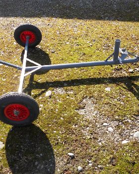
Before I describe my new steering arrangment, I wish to thank Paul and everyone else for their effort to produce the drawings for the class 5 sailer. What a superb job.
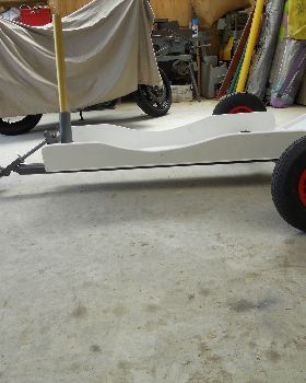
I have studdied every drawing and comment I could find about steering geometry and the angled rear axle tubes, the "Y" design. It was very interesting to read that for the most part, the swept back axle tubes offered greater speed and quality of ride. I have no idear why a higher speed is obtainable but I offer my two cents worth as to why better riding qualities seem to be the thing with swept back axles. I suggest it is because of having a much longer axle tube as a swept back style. For the same wheel track as the class 5 drawn by Paul, the straight "T" axle is 400mm shorter on each side.
This 400mm extra length in the sweep back may offer more flexing, hence more shock absorbing qualities (IM humbleO). As for performance enhancement, the "Y" shape might offer a better center of mass position. As for any other of my thoughts, I am all out of them and at your mercy.
Now for my new steering arrangement,
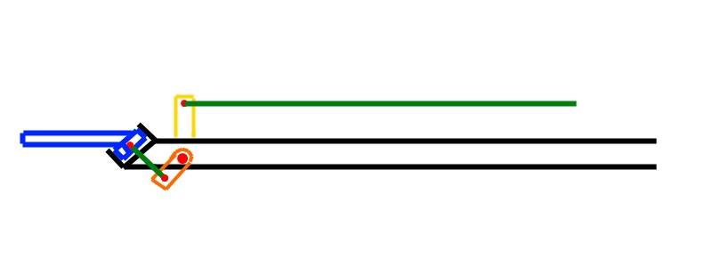
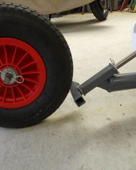
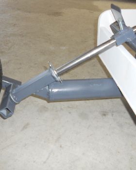
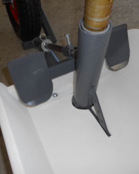
I have decided to go with the "laid back" style of steering tube and will set it up at 35 degrees. The foot steering bar swings in a true horizontal motion and is coupled to the tube via a unique lever system using only one more set of combined levers. There is no slop or play in the system and the push rods swing in an arc of no more than four degrees either side for left or right. The actual wheel will rotate to 60 degrees on either side. Is 60 degrees enough? not enough? or just right? Any greater than 60 degrees and I think you would go end over turkey as it were. It is very hard to explain without a picture exactly how this will opperate and even worse, I don't have 3D ability on my CAD program.

I have never seen an example of this arrangement before, so it may not have been used before. I can't wait to actually build the structure and display some photos for you all. I will try and describe the basics of how it works.
As you swing the foot bar, a connecting rod is moved forward and backward in a horizontal plane. This rod is coupled to a short lever on the LHS that pivots from under the frame and is fastened to another lever on the opposite side (the RHS). The length of the levers' axle is only 70mm or less. From the other side (the RHS) the final push rod is connected to the steering tube. (now wasn't that simple?

). A photo is a definite must so you can understand all this. Anyway, I have absolute confidence in my design and if I have to hand draw it then I will do so. The secret, as you all know, for absolute success with any linkage system is to have all the angles of the rods and levers set up in exactly the correct position.
I have a set of Fallshaw wheels lined up and I hope to get them in my eager hands within two weeks.
Kody