I am interested in learning more about the Mini landyachts discussed in this forum.
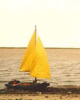
I usually approach design problems by putting numbers onto a spreadsheet. Each line drawn requires answers to why and where things go. The decisions become mathematically linked together and what results is a parametric model that begins to look like something, in this case a sail. I started with the design presented by BenBoulder in the topic, 4.6 Mini Sail.
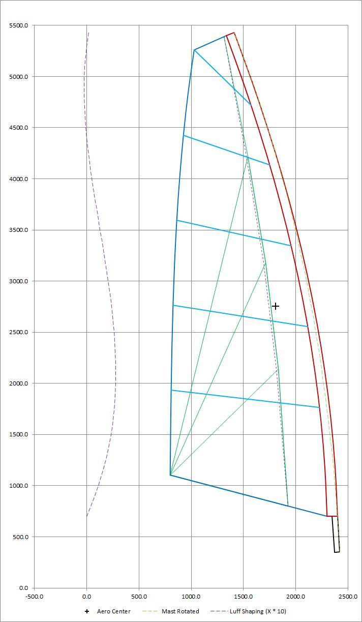
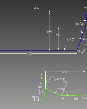
Here are the inputs and outputs for my first attempt. Any input(s) may be changed and the rest will automatically recalculate. The mast bend is a circular arc and there is no allowance for draft. I hope to get a little more information before finalizing these.
Please have a look, could be worthwhile.
General Luff panel LE Circular arc. This shape also defines the Mast curve.
Battens 5 Battens on sail extending from the Leech TE to the Luff pocket TE
4 Battens oriented horizontally and distributed evenly on the vertical span limited by the Head and Foot TE on the Leech.
Batten 5 is oriented below horizontal joining the Head TE to the Batten 4 LE.
Aft panels Area behind Luff panel divided into three triangles and one trapezoid (upper).
The peaks of the three radial panels are located along the Z dimension of the Leech (quarters).
The peaks of the three radial panels are located along the X dimension at the same fraction of their local chord behind the Sail LE.
Luff panel overlap When laid flat the Luff panel TE overlaps the Radial panel LE allowing for sail draft.
There is no overlap at the intersections with the Head and Foot.
Overlap determined as a percentage of the average sail chord between the Head and Foot TEs, applied to the local chords at the three radial panel peaks.
Input Mast Origin (X) 2500.0 mm
Origin (Z) 0.0 mm
Diameter 50.0 mm
Rake 10.0 deg
Luff pocket Origin (Z) 500.0 mm
Luff pocket flattened 100.0 mm
Ratio of full to flattened 0.67
TE end to end (chord of arc) 4650.0 mm
TE peak at chord center 185.0 mm
Aft panels LE Location on local sail chord line 0.30
Luff panel TE overlap Overlap at average sail chord between the Head and Foot TEs 0.0 mm
Note: Sail is currently flat
Exterior Layout Foot length 1445.0 mm
Foot angle -10.0 deg
Leech 3945.0 mm
Head 440.0 mm
Output LayoutSail area 4.595 m^2
Centroid (X) 1315.5 mm
Centroid (Z) 2416.0 mm
Aspect Ratio 4.25
Leech angle 96.9 deg
Head angle 31.2 deg
Luff panel LE angle (end to end) 109.0 deg
Radial panel 1 (bottom) Length along Foot 1062.9 mm
Length along LE 1185.7 mm
Length along top 1277.0 mm
Radial panel 2 Length along Radial panel 1 1277.0 mm
Length along LE 1008.6 mm
Length along top 2041.9 mm
Radial panel 3 Length along Radial panel 2 2041.9 mm
Length along LE 1023.0 mm
Length along top 2951.1 mm
Trapezoid panel 1 (top) Length along Radial panel 3 2951.1 mm
Length along LE 1264.2 mm
Head 440.0 mm
Length along Leech 3945.0 mm
Diagonal-Head TE to Radial 3 Peak 1235.0 mm
Luff panel Length on Foot 382.1 mm
Length Foot LE to Head LE (straight) 4650.0 mm
Length on Head 57.8 mm
Length on TE (straight) 4461.0 mm